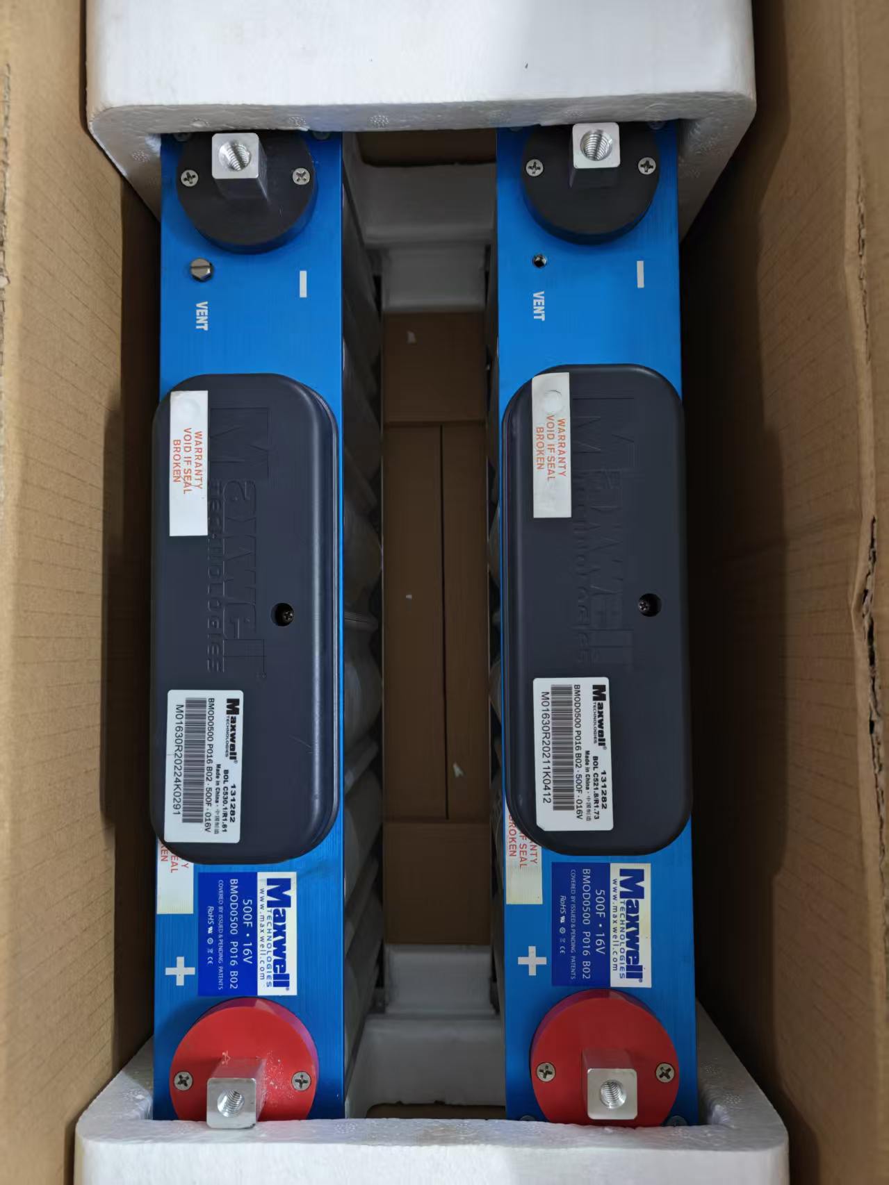
Designing a reliable EDLC supercapacitor module requires careful attention to cell balancing, voltage matching, and thermal management. Unlike batteries, supercapacitor cells have tight voltage tolerances (typically 2.7V or 3.0V per cell), and even small mismatches can cause overvoltage failures in series strings. In this engineering guide, we cover the critical design principles for building long-lasting, high-performance supercapacitor modules.
Why Cell Balancing Is Critical
When supercapacitor cells are connected in series to achieve higher voltages, each cell must share the total voltage equally. However, due to manufacturing tolerances, differences in capacitance (±10–20%), internal resistance (ESR), and self-discharge rates cause voltage imbalance across the string. Without balancing, the cell with the lowest capacitance will charge to a higher voltage first, potentially exceeding its rated voltage and causing permanent damage or catastrophic failure.
Example: A 6-cell 16V module using 2.7V cells. If one cell has 10% lower capacitance, it may reach 2.9V while others are at 2.65V — exceeding the 2.7V rating and shortening lifespan by 50% or more.
Passive vs. Active Cell Balancing
| Method | How It Works | Advantages | Disadvantages | Best For |
|---|---|---|---|---|
| Passive (Resistor) | Bleeds excess charge through a resistor when cell voltage exceeds threshold | Low cost, simple, reliable, no inductors | Energy wasted as heat, slow balancing, only dissipative | Low-to-medium power modules, cost-sensitive applications |
| Active (Capacitor) | Transfers charge between cells using flying capacitors | Energy efficient, faster balancing | More complex, higher cost, switching noise | Medium-to-high power modules, energy-critical applications |
| Active (Inductor) | Uses inductors to transfer charge between cells | Highest efficiency, fastest balancing | Highest cost, complex control, EMI concerns | High-power systems, automotive, grid storage |
At XDXT Electronics, our standard 16V supercapacitor modules use integrated passive balancing with precision voltage monitoring. For custom high-voltage banks (48V+), we recommend active balancing for maximum efficiency and lifespan.
Voltage Matching: The Key to Long Module Life
Voltage matching ensures that all cells in a series string charge and discharge uniformly. Best practices include:
- Cell sorting — Match cells within ±2% capacitance and ±5% ESR before assembly. We pre-sort all cells used in our modules.
- Balancing threshold — Set passive balancing to start at 2.65V (98% of 2.7V rating) to prevent any cell from exceeding rating.
- Overvoltage protection — Add Zener diodes or active crowbar circuits at 2.85V per cell as a final safety layer.
- Undervoltage protection — Prevent cells from discharging below 0.5V to avoid capacitance degradation.
Series-Parallel Configuration
Module voltage and capacitance are determined by the series-parallel configuration:
- Series (N cells): Voltage = N × V_cell, Capacitance = C_cell / N
- Parallel (M cells): Voltage = V_cell, Capacitance = M × C_cell
- Series-Parallel (N×M): Voltage = N × V_cell, Capacitance = M × C_cell / N
Example: A 16V 500F module using 2.7V 3000F cells requires 6 cells in series (6 × 2.7V = 16.2V) with 1 parallel string (3000F / 6 = 500F). This is exactly how our 16V 500F module is configured.
ESR Matching and Thermal Design
Internal resistance (ESR) matching is critical for high-current applications. Cells with higher ESR will dissipate more heat (P = I² × ESR), creating hot spots that accelerate aging. Design considerations:
- ESR matching — Match cells within ±5% ESR for high-current modules
- Thermal coupling — Ensure all cells have equal thermal resistance to the heatsink or ambient environment
- Current derating — For continuous operation, limit current to 50–70% of the cell's peak current rating
- Temperature monitoring — Add NTC thermistors at multiple points in the module for overtemperature protection
Module Testing and Quality Control
Every XDXT Electronics supercapacitor module undergoes rigorous testing before shipment:
- Capacitance test — Measured at constant current discharge, verified within ±10% of rated value
- ESR test — Measured at 1kHz AC, verified within specification
- Leakage current test — Held at rated voltage for 30 minutes, leakage current must be below specification
- Balancing verification — All cells monitored during charge/discharge cycles, voltage imbalance must be <50mV
- Thermal cycling — -20°C to +65°C cycling for high-reliability modules
Custom Module Design Service
Need a custom voltage, capacitance, or form factor? Our engineering team can design and manufacture custom supercapacitor modules to your exact specifications. We offer:
- Custom voltages from 5V to 500V+
- Custom capacitance from 1F to 100,000F+
- Integrated balancing, protection, and monitoring circuits
- Custom mechanical design for your enclosure
- Full documentation including datasheets, test reports, and application notes
Contact us via WhatsApp with your specifications, and our engineering team will provide a custom module design and wholesale quotation within 24 hours.
Conclusion
Designing a reliable supercapacitor module requires careful attention to cell balancing, voltage matching, ESR matching, and thermal design. By following these engineering principles and using pre-sorted, quality-tested cells, you can build modules that deliver 500,000+ cycles and 10+ years of reliable operation. Whether you choose our standard 16V modules or need a custom design, XDXT Electronics provides the engineering expertise and quality control to ensure your supercapacitor system performs reliably for years.